PCB component reference
A practical PCB component guide — passives, ICs, connectors and protection, with packages, values and decoupling notes. Free on brahm.design.
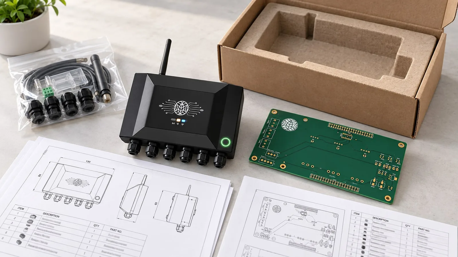
Most early schematic mistakes are ordinary: a missing decoupling cap, a pull-up on an open-drain net, a connector without a strain plan, or a protection device in the wrong place. The component reference is a catalogue of common PCB parts — passives, ICs, connectors and protection — with the values, packages and placement notes that usually matter at the schematic stage.
Bypass and bulk capacitors, pull-ups, series resistors, ESD devices and a first LDO or module are the kind of entries you will find, written as design reminders rather than as a distributor search. A 100 nF X7R next to a digital power pin, a bulk cap at a board entry, and an ESD device at a connector with a short path to chassis or a ground plane are not advanced ideas, but they are easy to skip under time pressure.
Package choice is part of the same decision. 0402 may be right for a dense digital board and wrong for a hand-soldered prototype or a high-voltage creepage path. The notes are starting rules. Always read the manufacturer’s datasheet for pinout, derating, polarity and the recommended land pattern, and always check voltage rating, temperature coefficient and dielectric (X7R, C0G, and so on) for capacitors.
Use this reference to start a schematic cleanly, then use the schematic guide and the DRC checklist before you send a board out.
Example
A default that is still worth placing on purpose. A microcontroller with three power pins: one 100 nF X7R on each pin, vias to the plane as close as the land allows, plus bulk capacitance at the regulator output as the datasheet asks. The reference exists so that this pattern is a decision, not an afterthought in layout when the ratsnest is already a mess.
How to use this tool
- Open Component Reference and browse the family you are placing, or search for the function (decoupling, ESD, pull-up).
- Read the placement and package notes before you drop a default library part into the schematic.
- Check the datasheet for the exact part number you will buy — value, voltage, dielectric and land pattern.
- Place decoupling and protection at the pins and connectors they serve, not in a leftover corner of the sheet.
- Run the schematic guide against the finished sheet.
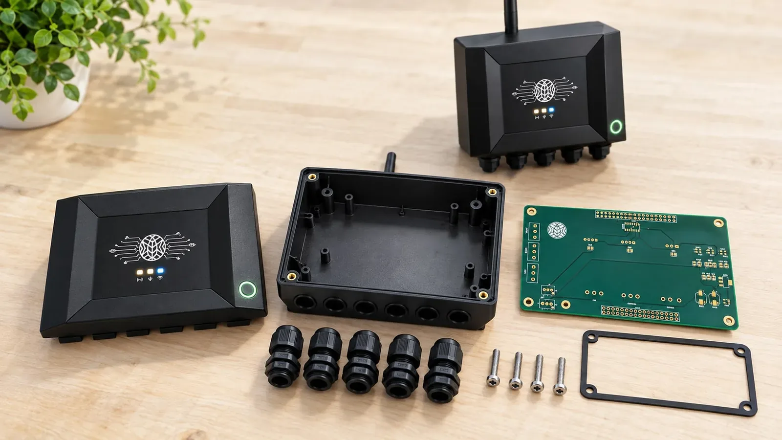
Frequently asked questions
Is this a full part catalogue?
No. It is a design-oriented subset of common parts and practices, not a distributor inventory and not a substitute for a datasheet.
Do you recommend specific manufacturers?
The notes are about types and practices (for example a 100 nF X7R in 0402 near a power pin). Choose a manufacturer and a part number from a source you trust, with stock and qualification in mind.
Are the decoupling rules enough for a switch-mode regulator?
They are the usual minimum for digital ICs. Switching regulators have layout and capacitor requirements in the datasheet that you should follow exactly, including layout examples.
Can I rely on this for medical or automotive parts?
Use it as a reminder, then follow the relevant standard, your company’s AVL, and the qualification the project requires.