IPC-2221 PCB trace width calculator
Calculate minimum PCB trace width from current, copper weight, layer and temperature rise using IPC-2221. Free calculator on brahm.design.
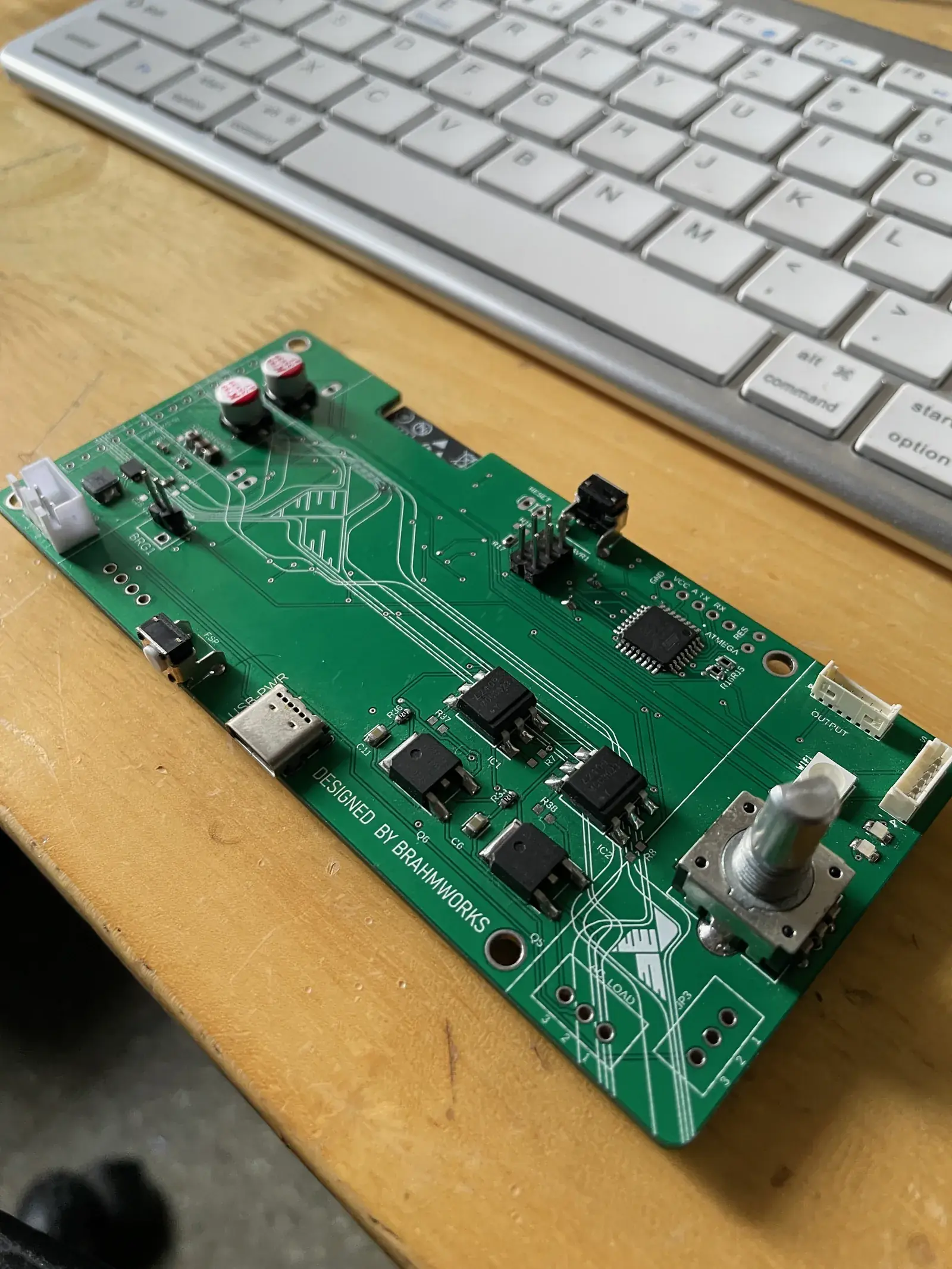
A trace that carries current has to be wide enough not to overheat, and often also thick or wide enough not to drop too much voltage. This calculator estimates the minimum copper width for a given current using the IPC-2221 current-capacity relationship, with separate constants for external and internal layers and an adjustable temperature rise. You can also enter a length to see a first-order resistance, voltage drop and power loss in the copper.
IPC-2221 is still the relationship many fab notes and textbooks cite. In the form used here, the required cross-section is A = (I / (k · ΔT^0.44))^(1/0.725), with A in square mils, k = 0.048 for external (outer) layers and k = 0.024 for internal layers, and ΔT the allowed temperature rise in °C. Width is then A divided by the copper thickness (1 oz copper is taken as 1.378 mil). Internal layers shed heat less effectively, so they come out wider for the same current and rise.
Treat the result as a minimum, then add margin. A common practice is to design 25–50% wider than the IPC-2221 minimum, and to check voltage drop on long power runs separately — a trace can be thermally acceptable and still drop too many millivolts into a rail. The calculator’s drop and loss figures use a copper resistivity of 1.72×10⁻⁸ Ω·m and the finished width, which is enough for a first pass, not for a precision sense resistor.
IPC-2152 is a newer and generally more detailed current-capacity standard, and many teams now prefer it or a vendor chart, especially for heavy copper or unusual stackups. This tool is honest about using IPC-2221. For high-current, high-reliability, or IPC class 3 work, confirm with the standard you are contracted to, the copper roughness and the actual stack, and your fab’s chart. The calculator also does not size traces for controlled impedance — use the stackup builder and an impedance tool for that.
Key relationship
A (mils²) = (I / (k · ΔT^0.44))^(1/0.725)
k = 0.048 (external) or 0.024 (internal)
Thickness ≈ 1.378 mil per oz; width = A / thickness.
R = ρ L / A, with ρ_copper ≈ 1.72×10⁻⁸ Ω·m (first-order drop and loss).
Try a basic IPC-2221 estimate
This public preview uses the same relationship as the full toolkit. Open the toolkit for length, drop and the rest of the PCB tools — no account needed.
IPC-2221 minimum, then a 25% margin. Confirm high-current or Class 3 work with the standard you are contracted to. Not for controlled impedance.
How to use this tool
- Enter the current, copper weight (oz), whether the trace is on an external or internal layer, and the temperature rise you can allow (10 °C is a common starting point, not a law).
- Optionally enter the length if you also care about voltage drop.
- Read the IPC-2221 minimum width and the 25% margin suggestion.
- Check the drop against your rail budget. If the drop is the limiter, widen the trace or shorten the run; do not only trust the thermal width.
- Put the chosen width, copper weight and layer on the drawing or in the design rules, and confirm with your fab if the current is high.
Frequently asked questions
Why is an internal trace wider than an external one?
Internal copper is buried in dielectric and cannot radiate or convect as easily. IPC-2221 uses a smaller k for internal layers, which increases the required cross-section for the same current and rise.
Should I use IPC-2221 or IPC-2152?
This calculator implements the widely used IPC-2221 relationship. IPC-2152 is newer and often considered more accurate. Use the standard your project or customer specifies, and treat this result as a first estimate if you are on 2152.
Does this set the width for a 50 Ω line?
No. Controlled impedance depends on geometry, dielectric and reference planes. Use this tool for current capacity; use a stackup and an impedance calculator for high-speed or RF lines.
What temperature rise should I pick?
It depends on the ambient, the glass transition of the laminate, nearby components, and the reliability target. 10 °C is a conservative common starting value; some power designs allow more with analysis. Do not pick a rise that takes the copper or the board past your material limits.