PCB design brief generator
Generate realistic PCB design briefs — power supplies, IoT modules, motor drivers and RF boards — to practise a full design pass. Free to use.
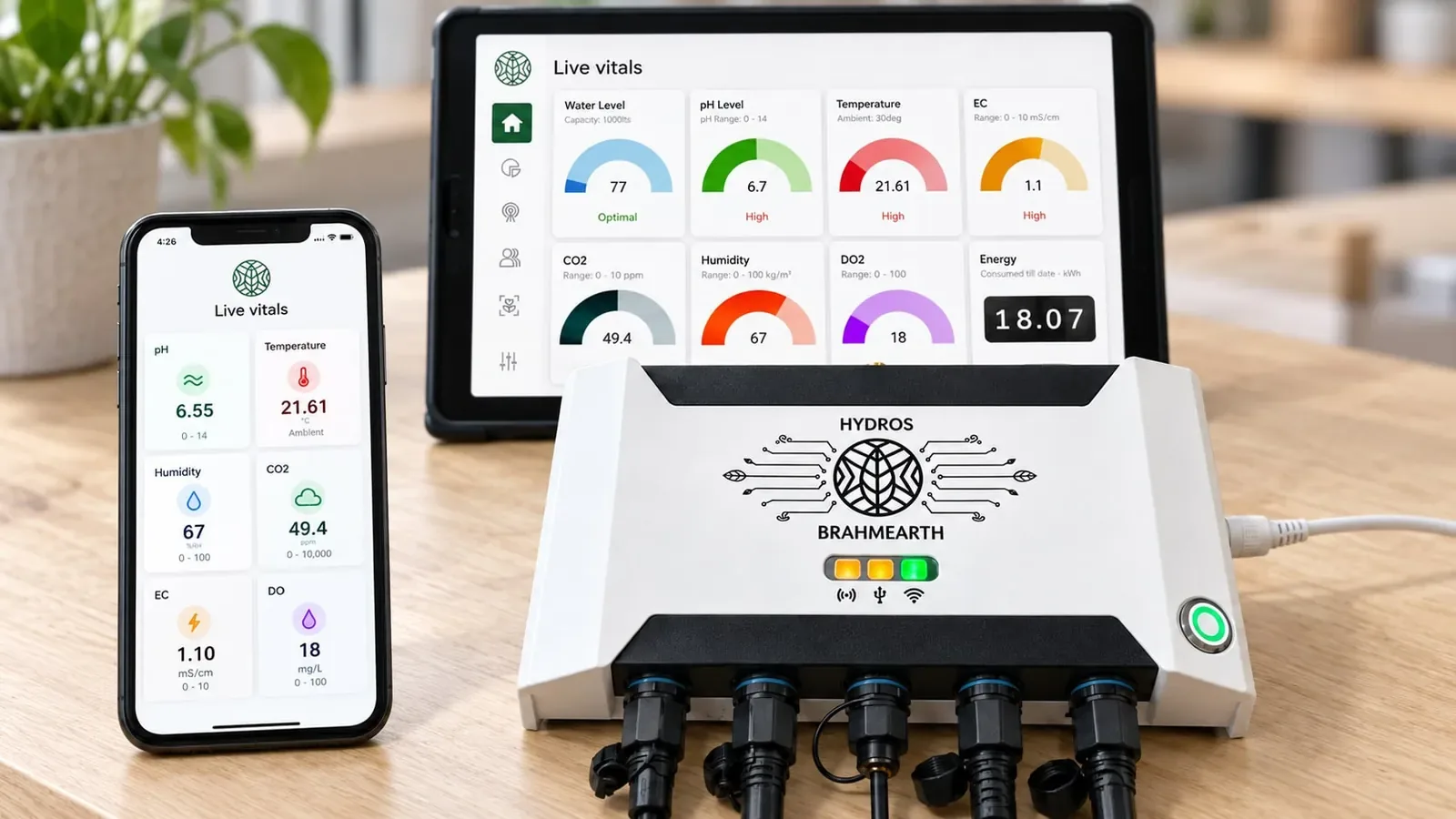
Board design is practised by taking a brief to a schematic, a stack, and a release list. This generator produces realistic PCB practice briefs — a power supply, an IoT module, a motor driver, an RF board, and similar — with enough constraints (rails, connectors, environment, volume) to force a complete pass rather than a doodle in CAD.
Use a brief as a weekend or interview-prep exercise: restate the requirements, draw a block diagram, choose a stack, list the protection and the programming hook, and write the DRC and test plan. Label it as practice if it ever appears in a portfolio. The other tools in this toolkit — trace width, component reference, schematic guide, DRC, stackup — are meant to be used during that pass.
A useful output always includes a power architecture and a bring-up plan. A pretty board file with no test points and no idea how the first article will be powered is not a finished exercise.
For professional work, the brief has to come from the real product, the real standard (including medical, automotive or radio certification if they apply), and the real cost. Use the generator as a gym, not as a substitute for a requirements document.
Example
A brief you can complete. “An IoT node: mains-to-5 V on the same board, an ESP32-class module, two sensors on I2C, a USB serial and programming port, and a cheap two- or four-layer stack, indoor use, 2,000 units.” A complete practice pass has a block diagram, a protection and isolation decision at the mains input if you keep it on-board (or a formal note that you used a certified brick), decoupling, ESD on USB, and a bring-up order. That is the habit the generator is for.
How to use this tool
- Generate a brief and rewrite the requirements, including hidden ones (programming, test, enclosure, cable).
- Draw a block diagram and a power tree before you open the schematic editor.
- Choose a stack and a first DRC set that match the brief’s speed and environment.
- Walk the schematic guide and the DRC checklist as if you were going to order three boards.
- Write a bring-up list: rails to measure first, firmware hook, and what would make you stop and rework.
Frequently asked questions
Are these real product briefs?
They are realistic practice scenarios (power, IoT, motor, RF and similar), not confidential customer documents. Do not present them as commissioned work.
Can I choose the difficulty?
Generate until you get a scope you can finish in the time you have, or edit the constraints. A smaller brief finished properly is better than a radio plus a motor driver left half-drawn.
Does the brief include a schematic already?
No. The work is yours. The toolkit’s reference material is there to support it.
Is there a correct stack for every brief?
There is a defensible one. Write why you chose two, four, or more layers, and what you would change at the next volume or EMI test.